In this section we will have short but powerful introduction to Blender. We will cover just enough of model creation basics, you will need to create most of simple projects.
No, we will not cover animation, shaders or modificators here, but just enough minimum to create this ramp floor for our tutorial:

You will find lot of keyboard shortcuts here. And this is one of the most awesome features of Blender - you can work without menus or panels! Everything you need can be done with keyboard!
So let’s dive in Blender now!
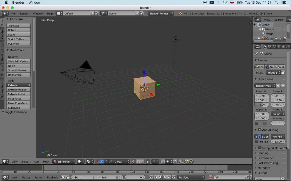
Welcome to Belnder
When you open Blender, you will see some pretty image, made with Belnder, version information, some useful links and recent files

To close this window, simply click outside it. You will then see your workspace with the
Default window layout (we will learn about them later). Workspace contains a few kickstarting
items:
- camera
- light
- cube

You may be confused of the last one, but you will see shortly that so many cool things could be done starting with plain cube and modifying it. Oh, and about modifying: let’s switch to the Edit mode, hitting the Tab key:
You can exit it hitting Tab again. In the edit mode you can manipulate mesh’ edges, vertices or faces. To switch between these, use three buttons on the screen’s bottom:

Let’s choose the faces editing mode. Unlike other 3D editors, in Blender selection is done with the Right mouse button. Select one face of the cube:

You may have noticed that the axis arrows have moved in the selected face’s place. These are used to manipulate selected elements. Also, they show the orientation of the selected element. You can move the selected element by simply dragging one of the arrows. Selected element will be moved along the selected axis only:

The same operation, movement, could be performed hitting the G key. You can move other elements, too - this will change the form of our cube:

Now let’s try something more complex. See the Tools panel on your left?

Select a face in a face editing mode and click Extrude (or hit the E key). Your face will be extruded and you will be able to move it freely. But usually, designers move elements along some axis - this makes models more accurate. To fix the movement axis, just hit its letter while being in the extruding mode - X, Y or Z:

Interesting fact: you may extrude both vertices and edges too.
Now, let’s use even more advanced operation, which is oftenly described later in tutorials on 3D modelling. Choose the Loop cut and slice operation from the Tools panel - you will see nothing. Until you move your cursor over your model. Depending on the edge, cursor is closer to, you will see purple rectangle, looping through your model:

When you click the Left mouse button, you will move to the next part of this operation - slicing. Just place the new edges where you want:

Now let’s create walls for our “ramp”. Create a few loop cuts alongside the ramp and we will start extruding:

Or maybe just moving faces?..

No, that’s definitely not what we want! We want walls, not a new ramp! Hmmm… But if we will extrude walls one-by-one, it will be inaccurate… Hold the Shift key and right-click the two neighbour walls:

Now we will work with three elements in the same way. Hit the E key and then - Z and extrude all three walls at the same time up:

Now we need two more walls to prevent our hero (the ball, if you recall from the previous part) from falling aside. Select two edges at the corner of our ramp and hit the W key. You will see the context menu like this:

Click the Subdivide item, and the selected edges will be connected right in the middle:

You can perform that operation on faces - that is oftenly handy. Now, if you undo your changes with usual Ctrl+Z (or Command+Z on Mac) and try to perform the same operation on four opposite edges, you will see there is a redundant (in our case) edge:

You can remove it by selecting that edge, hitting X and selecting Dissolve edges. If you choose the Delete edge - you will loose the neighbour faces, which were made of that edge.

So in the end we need to have two edges on the same line:

Now, switch to the Ortho View, choosing one from the View menu at the bottom of the screen, or hitting the Num 5 key:

Your workspace now should look different:

Using the View menu, you may switch between different views, perpendicular to your model.


Switching between different views will not clear the selection. And this is awesome! So if you try to move the selected edges in the Right Ortho View, you will move both of them:

Yeeks… They move just along the Y axis, but not along the edge. But Blender easily handles that - you need to switch between coordinate system using the corresponding menu at the bottom of your screen:

Use the Normal one and you will see the arrows at the selected edges changed:

Now movement is done along the edge, just as we need:

Try moving (yes, moving, not extruding) our edges up - they will move along the normal:

But if you click the mouse wheel and rotate camera, or even if you switch to the Top Ortho view, you will notice that our walls have different width:

So we need to make one wall thinner. But we should not forget about other edges - ones, which will make another wall for us. Undoing now is not an option… We need to move the edges. But if you move only those visible at the Top Ortho view, you will forget about the ones at the bottom and screw the model. And selecting all those edges one-by-one is not an option too…

Moreover, we do not see those edges at the bottom! This is easy to fix, though: see the small button with rectangles near the vertex/edge/face switcher?

Click it and you will be able to select bottom edges without the need to rotate the camera. And now we will try the circle-selection tool, which will come to help you when you need to select many elements at a time. Hit the C key and you will see the circle in a workspace. Try dragging it (left-click the mouse and drag) over the edges we need:

Hmmm… It’s way too much… Now, hold the Shift key and drag the circle over the neighbour, redundant ones:

Now we can switch back to the Top Ortho View and successfully move our edges:

Now that we have our walls precisely set up, we can extrude the last two walls. Select the Normal coordinate system and perform the extrusion along the Z axis:

Now we will scale our model a few times. Staying in the Edit mode, select all the faces with the A key:

And hit the S key and start entering scale factor number. That’s right, just press, say, 5:

You can correct what you entered using the Backspace key. You can do the same thing while moving or rotating elements. This is useful when you need to make operation really precise. But you still can use your mouse, of course.
Hint: if you scaled your model outside the Edit mode, you may find your scale, translation
or rotation different from identity values (1, 1, 1 for scale or 0, 0, 0 for position/rotation).
This may cause different bugs while exporting models. To fix this, you need to select your
model in the Object mode, hit the Ctrl+A and select Apply Scale
(or whatever you need to fix) from the pop-up menu.

Texturing our model
Now we need to paint our model to have something more beautiful in our application than just pitch black… stuff…
Adding textures to a model in Blender is extremely easy - you just select your model, switch to the Texture tab on the right panel and click New button:

Then you pass in some params like texture size, the background color and image name - and you are done!

But that will only add a blank texture. And then you will need to paint it as you wish.
But painting a texture requires your model to have vertices, synchronized with your texture.
So each vertex will know where it lays both in 3D space and on the texture image. This
assignment process is called Texture unwrapping or UV mapping (because texture
coordinates are usually called u and v instead of x and y, since those are already
involved to describe vertex’ position). And this process requires one thing from you: you
need to specify, where Blender should “cut” your model. This is quite simple task, but this
will result on how the texture will look like and how easy it will be to paint.
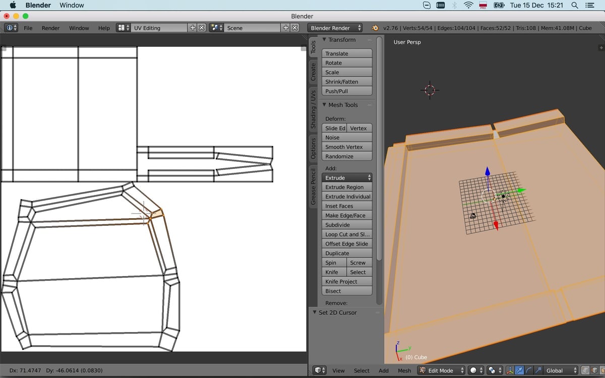
So, go to the Edit mode and select a few loops of edges:


Now, on the left panel, switch to the Shading/UVs tab and click the Mark Seam button:

This will mark the selected edges as seams to “cut” your model along. Have no fear, your model will not be actually cut - it will be used for maths only.
Then, on the same panel click the Unwrap button and select the first unwrapping method on the list:

Again, no effect you will see now. To see something, switch the window layout at the top menu to UV Editing:


You will see two windows - on your left there will be UV/image editor and on your right there will be the 3D view. And again, nothing interesting here… But I am not fooling with you - it’s only how Blender works… To see something marvelous, select everything on the 3D view:

You will see some lines on your left. That’s what you have selected, mapped onto image plane. But there is no actual image in the UV/Image editor for now. To add one, just click the New button on the bottom menu of the UV/Image editor or select an existing one:

This will not change the image itself. The image will be the background for our image editor window, nothing more. To start making miracles, go to the Texture Paint mode in the 3D view:

And your model will change its look…

What is this pink monster?! Well, on the left panel of our 3D View there’s a message, saying the texture slot is missing and proposing to create one… Let’s do this…

Now we are able to paint our model! See, how awesome it is: you have a brush tool activated. Brush has three params:
- Color - this could be changed with the color circle below
- Radius
- Pressure, or Alpha
Radius could be changed by pressing the F key and moving mouse cursor:

Pressure could be changed by pressing Shift+F and doing the same:

And you can just pain like in… Microsoft Paint!

But if you look into the UV/Image editor, you will see… nothing! Again! ‘the hell?!

That is just misunderstanging - you were painting on the other image instead of the selected one:

We created a new one, when created a texture slot…
To start drawing in the UV/Image editor instead of 3D View, you just need to switch its mode to Paint at the bottom menu:

Okay, so far so good. We are able to paint our model. But there’s one interesting thing: if you try to draw a straight line - you may face situation, when line is straight in the image but is curved on the model:


But that’s happening not everywhere - only on certain faces/edges:

Well, that’s because of UV mapping is not precise enough. If you switch to the View mode in the UV/Image editor and to the Edit mode in the 3D View, and select all the model, you will see the points in the image editor, you may drag:

Try selecting them with Right mouse button and moving them with G:

Yes, now texture looks creepy, but lines are almost straight:


Exporting our model
When you finish painting your texture, the last thing we need to do is to export our model to the format, understandable by Irrlicht. For good, both Blender and Irrlicht support many different formats:

Blender’s file dialogs look differently, but have very intuitive interface:

If you do not see the needed format in Blender - you just need to turn on a corresponding plugin:


After exporting our model to, say, 3DS format, take a look at the directory you have exported your model to:

Where are the textures? Relax, they are in the UV/Image editor, yet unsaved. You can save the modified image with the Image -> Save menu at the bottom of UV/Image Editor:

Now we have everything we need for our Newtonian sample!