Software Engineering 101: how computer works
There is some bit of information about computers which I was never told in school or at the university. This writing is trying to cover these bits in details for those interested out there.
Processor’s guts
In essence, processor consists of these main blocks:
- instruction decoder, which decodes the operation code (see below) and tells processor what it should do next
- ALU (arithmetical-logic unit) - the device, which performs all the operations a processor is capable of - arithmetic (addition, subtraction, multiplication) and logical (bitwise OR, AND, XOR, NOT; comparing numbers)
- registers are the places, where processor takes the input data for each operation and stores the results of each operations
- data bus - the place, which passes data to or from memory (RAM, peripheral devices and other types of memory)
- address bus passes memory addresses between processor and memory (to be read from or written to)
To best illustrate our examples, consider this much simplified processor model:
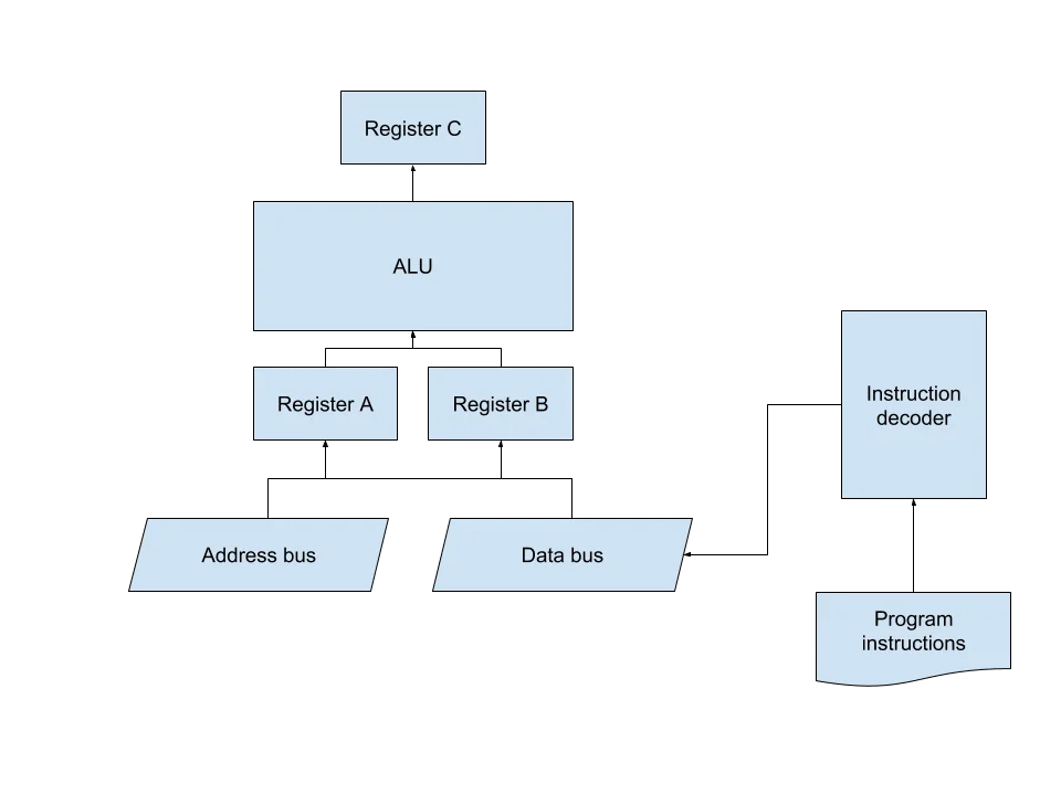
It has only three registers, ALU and data/address buses. I will explain all the examples below in reference to this processor.
Workflow
Processor works discretely, meaning it executes commands at certain points in time (as opposed to continuous work, where something works all the time). Those points in time are marked by clock signals (or simply, clocks). Processor is connected to (or has an internal one) clock signal generator, which regularly tells processor to operate. Operation is nothing but a change of the internal processor’ state.
So how does processor knows what to do next? On the first clock signal, CPU loads the command with the help of instruction decoder. On the next clock tick, processor starts executing an instruction (or a command) - it either copies data to / from registers or RAM, or involves ALU. On the next clock, processor increases the command counter by one and hence proceeds to the next instruction from the pool.
In reality, this mechanism is somewhat more complex and involves more steps to just even read the command from the pool. And the pool itself is a unit on a processor chip as well and acts as another register. But to explain the processor operation, I’ve simplified that.
Read more to where I explain how a program in Assembly language is transformed to ones and zeroes; show a sample processor instruction set and how a program in C could be compiled to that instruction set.
Assembly language
Each processor instruction is a chain of ones and zeros. Assume we have these commands processor can understand:
- adding the values in registers A and B and storing the sum in register C and the information about possible register overflow in register S (this occurs when we do not have enough memory in register to store the result: say we have only 4 bits in each register, then what will the sum of
1111and0001?10000, which takes5bits - more than we have in a register; we can then set the result to10000 - 1111 == 0001and proclaim “we have come over the size of register”) - subtract the values in registers A and B and handling overflows the same way as in addition (imagine subtracting 0001 - 0001 with only 4-bit-wide registers)
- multiply registers A and B
- divide registers A and B (A / B)
- perform bitwise operations AND, OR, NOT and XOR on registers A and B and store the value in register C
- set the value of a register (either A or B) to a specific constant value
- move a value from register C to either register A or register B
- load data from memory under the address specified to a specific register (A or B)
- save data from register A or B to a memory under the address specified
- compare the values in registers A and B and set the corresponding flag in register C (whether the values are equal or A > B or B > A)
- go to a specific instruction of a program
- go to a specific instruction of a program, based on comparison flags in register C
Let us name these commands:
ADD= A + B -> CSUB= A - B -> CMUL= A * B -> CDIV= A / B -> CNOTA= NOT ANOTB= NOT BAND= A AND B -> COR= A OR B -> CXOR= A XOR B -> CSHR= A >> B -> C (bitwise shift right)SHL= A << B -> C (bitwise shift left)MOV A, const= const -> AMOV B, const= const -> BMOV C, A= C -> AMOV C, B= C -> BMOV A, C= A -> CMOV B, C= B -> CLOAD addr, A= memory[addr] -> ALOAD addr, B= memory[addr] -> BLOADB= memory[A] -> BSAVEB= B -> memory[A]CMP= A <=> B -> CJMP line= GOTO lineJL line= if A < B (from comparison flags in C) then GOTO lineJLE line= if A <= B then GOTO lineJEQ line= if A == B then GOTO lineJNEQ line= if A != B then GOTO lineJGE line= if A >= B then GOTO lineJG line= if A > B then GOTO lineNOP= do nothing
This is a great subset of Assembly language commands! Just think about it: you can actually represent pretty much any program using only these 30 instructions! All the modern processors’ instructions are mostly optimized variations of the commands listed above.
You can notice each command has its own number. We have fit all our commands in 25 numbers, which is great - in order to represent them in binary number we will only need 5 bits of data (2^5 == 32; 32 > 30). Now, commands have at maximum one argument. Let’s say it could be at maximum 8-bit number (both addresses and lines are numbers; and since processor can only operate numbers - constants are also only numbers; when you need to represent a number as a character or vice versa - just use its ASCII code). Hence we can define an operation code format:
- fixed-width number of 8 bits, containing instruction number
- optional 8-bit argument
Assembly language is not invented separatedly from processor design, so assume all the integrated units and transistors inside our processor are aligned in a way so that when a processor receives our operation code - all of its components begin to operate immediately, according to the operation logic. In other words, processor is designed in a way which allows it to “understand” operation and its argument and set the results of its execution straight in place, when it arrives at processor’s inputs.
Now let us describe the process of a program execution. The program will calculate the sum of some memory cells and store the result in a memory address:
int sum(int *a, int n) {
    int i = 0;
    int result = 0;

    while (i < n) {
        result = result + a[i];
        i = i + 1;
    }

    return result;
}
We now will represent this program in our simple Assembly language dialect. But first we need to design a few conventions, function call conventions. Our processor has a very limited number of registers, but is capable of operating a very big amount of RAM memory. This amount is actually determined by three factors:
- the size of an address bus, which determines the maximum memory address which can be represented using ones and zeros (and thus transferred to a processor via wires)
- the size of a data bus, which determines the maximum amount of data which can be sent to processor
- the capability of ALU, which determins the maximum amount of data which ALU can take in and give out
So if the address bus has the size of 8 bits, processor is only capable of addressing 2^8 == 256 memory cells. But if both data bus and ALU are capable of transporting and operating 32 bits of data - then the amount of data we are able to process is 256 cells of 32 bit == 256 * 32 == 8192 bits == 8 MB.
Back to our function call convention, we need to determine how function arguments will be passed in and how the results will be passed out. The better question is not “how” but rather “where” - we have either three registers or memory cells to choose from. Thus we can either pass up to two arguments to a function or act more clever - assume the program’ memory starts at 0x0000 and has the following format:
0x0000- the number of program arguments0x0000 + ((n + 1) * 8)- then-thargument
Then we need to determine how many arguments a function can take in and where to store the result of a function. Let us limit the amount of memory dedicated to function arguments to 10. Then we can determine the address of a function result: 0x0000 + ((10 + 1) * 8) == 0x0000 + 88 == 0x0058. Everything beyond this address is treated as a program internal memory (used for storing intermediate data, variables, etc.).
In order to define the GOTO operator better and not worry about line numbers we shall use labels (but only during composing programs - assume compiler will substitute them with the actual line number values). Labels will be used like this: LABEL_NAME: <instruction>.
It would also be nice to be able to comment out some code. To comment the line (and thus do not take it into account when processing) we will use the semicolon symbol: ; comment.
Now that we have everything we need to componse a full program we can finally translate our sum function in C to our Assembly dialect:
; program bootstrap:
; these 3 steps are done by the callee (operating system or other function)
; - load the number of arguments, 2, to memory[0x0000]
; - load the address `*a` to memory[0x0008]
; - load the value of `n` to memory[0x00F0]

; assumptions:
; - i <=> memory[0x0058 + 8] == memory[0x0060]
; - result <=> memory[0x0058] == memory[0x0058] - we can just use the defined-by-convention memory cell in-place

MOV A, 0x0060        ; A = &i
MOV B, 0x0000        ; B = 0
SAVEB                ; move B -> memory[A] <=> i = 0

MOV A, 0x0058        ; A = &result
MOV B, 0x0000        ; B = 0
SAVEB                ; move B -> memory[A] <=> result = 0

LOOP: LOAD A, 0x0060 ; i -> A
LOAD B, 0x00F0       ; n -> B
CMP                  ; A <=> B => C
JGE RETURN           ; if i >= n then GOTO RETURN

LOAD B, 0x0060       ; B = i
MOV A, 0x0004        ; A = 4
MUL                  ; C = A * B <=> C = i * 4
MOV C, A             ; A = C <=> A = i * 4
MOV B, 0x0004        ; B = *a (the beginning of array `a`)
ADD                  ; C = A + B <=> C = &a + i * 4 == a[i]
MOV C, A             ; A = a[i]
LOAD B, 0x0058       ; B = memory[0x0058] <=> B = result
ADD                  ; C = A + B <=> C = result + a[i]
MOV C, B             ; B = C
MOV A, 0x0058        ; A = &result
SAVEB                ; memory[0x0058] = B <=> result = B <=> result == result + a[i]

LOAD 0x0060, B       ; B = i
MOV A, 0x0001        ; A = 1
ADD                  ; C = A + B <=> C = i + 1
MOV C, B             ; B = C <=> B = i + 1
MOV A, 0x0060        ; A = &i
SAVEB                ; memory[0x0060] = B <=> i = B <=> i = i + 1

JMP LOOP             ; GOTO LOOP

RETURN: NOP          ; program shutdown:
                     ; store the `result` value in memory[0x0058] - we operate on `result` through this address already, nothing to do here
For processor to run this code it needs to be compiled to opcodes first. For example, the MOV A, 0x0060 instruction will be converted (according to our convention) as:
0000 1100    0110 0000
~~~~~~~~~    ~~~~~~~~~
    ^            ^
    |            |
    |    0x0060 -┘
    |
    └- MOV A, const
To quickly recap, here is our processor instruction list together with its opcodes:
| No. | Instruction | Operation code |
|---|---|---|
| 1 | ADD |
0000 0001 0000 0000 |
| 2 | SUB |
0000 0010 0000 0000 |
| 3 | MUL |
0000 0011 0000 0000 |
| 4 | DIV |
0000 0100 0000 0000 |
| 5 | NOT A |
0000 0101 0000 0000 |
| 6 | NOT B |
0000 0110 0000 0000 |
| 7 | AND |
0000 0111 0000 0000 |
| 8 | OR |
0000 1000 0000 0000 |
| 9 | XOR |
0000 1001 0000 0000 |
| 10 | SHR |
0000 1010 0000 0000 |
| 11 | SHL |
0000 1011 0000 0000 |
| 12 | MOV A, const |
0000 1100 xxxx xxxx |
| 13 | MOV B, const |
0000 1101 xxxx xxxx |
| 14 | MOV C, A |
0000 1110 0000 0000 |
| 15 | MOV C, B |
0000 1111 0000 0000 |
| 16 | MOV A, C |
0001 0000 0000 0000 |
| 17 | MOV B, C |
0001 0001 0000 0000 |
| 18 | LOAD A, addr |
0001 0010 xxxx xxxx |
| 19 | LOAD B, addr |
0001 0011 xxxx xxxx |
| 20 | LOADB |
0001 0100 0000 0000 |
| 21 | SAVEB |
0001 0101 0000 0000 |
| 22 | CMP |
0001 0110 0000 0000 |
| 23 | JMP line |
0001 0111 xxxx xxxx |
| 24 | JLE line |
0001 1000 xxxx xxxx |
| 25 | JL line |
0001 1001 xxxx xxxx |
| 26 | JEQ line |
0001 1010 xxxx xxxx |
| 27 | JNEQ line |
0001 1011 xxxx xxxx |
| 28 | JGE line |
0001 1100 xxxx xxxx |
| 29 | JG line |
0001 1101 xxxx xxxx |
| 30 | NOP |
0001 1110 0000 0000 |
We will also need to extract only effective lines from our code and number each line (in order to operate with JMP-like instructions). And then all we need to do - is to substitute the commands in the source code with the ones from a table above and replace all those xxxx xxxx values (which stand for 8 bits of instruction’ argument):
| Line no. | Code | Instruction code | Argument | Argument (binary) | Instruction + argument |
|---|---|---|---|---|---|
| 0 | MOV A, 0x0060 |
0000 1100 xxxx xxxx |
0x0060 |
0110 0000 |
0000 1100 0110 0000 |
| 1 | MOV B, 0x0000 |
0000 1101 xxxx xxxx |
0x0000 |
0000 0000 |
0000 1101 0000 0000 |
| 2 | SAVEB |
0001 0101 0000 0000 |
0001 0101 0000 0000 |
||
| 3 | MOV A, 0x0058 |
0000 1100 xxxx xxxx |
0x0058 |
0101 1000 |
0000 1100 0101 1000 |
| 4 | MOV B, 0x0000 |
0000 1101 xxxx xxxx |
0x0000 |
0000 0000 |
0000 1101 0000 0000 |
| 5 | SAVEB |
0001 0101 0000 0000 |
0001 0101 0000 0000 |
||
| 6 | LOOP: LOAD A, 0x0060 |
0001 0010 xxxx xxxx |
0x0060 |
0110 0000 |
0001 0010 0110 0000 |
| 7 | LOAD B, 0x00F0 |
0001 0011 xxxx xxxx |
0x00F0 |
1111 0000 |
0001 0011 1111 0000 |
| 8 | CMP |
0001 0110 0000 0000 |
0001 0110 0000 0000 |
||
| 9 | JGE RETURN |
0001 1100 xxxx xxxx |
29 |
0001 1101 |
0001 1100 0001 1101 |
| 10 | LOAD B, 0x0060 |
0001 0011 xxxx xxxx |
0x0060 |
0110 0000 |
0001 0011 0110 0000 |
| 11 | MOV A, 0x0004 |
0000 1100 xxxx xxxx |
0x0004 |
0000 0100 |
0000 1100 0000 0100 |
| 12 | MUL |
0000 0011 0000 0000 |
0000 0011 0000 0000 |
||
| 13 | MOV C, A |
0000 1110 0000 0000 |
0000 1110 0000 0000 |
||
| 14 | MOV B, 0x0004 |
0000 1101 xxxx xxxx |
0x0004 |
0000 0100 |
0000 1101 0000 0100 |
| 15 | ADD |
0000 0001 0000 0000 |
0000 0001 0000 0000 |
||
| 16 | MOV C, A |
0000 1110 0000 0000 |
0000 1110 0000 0000 |
||
| 17 | LOAD B, 0x0058 |
0001 0011 xxxx xxxx |
0x0058 |
0101 1000 |
0001 0011 0101 1000 |
| 18 | ADD |
0000 0001 0000 0000 |
0000 0001 0000 0000 |
||
| 19 | MOV C, B |
0000 1111 0000 0000 |
0000 1111 0000 0000 |
||
| 20 | MOV A, 0x0058 |
0000 1100 xxxx xxxx |
0x0058 |
0101 1000 |
0000 1100 0101 1000 |
| 21 | SAVEB |
0001 0101 0000 0000 |
0001 0101 0000 0000 |
||
| 22 | LOAD B, 0x0060 |
0001 0011 xxxx xxxx |
0x0060 |
0110 0000 |
0001 0011 0110 0000 |
| 23 | MOV A, 0x0001 |
0000 1100 xxxx xxxx |
0x0001 |
0000 0001 |
0000 1100 0000 0001 |
| 24 | ADD |
0000 0001 0000 0000 |
0000 0001 0000 0000 |
||
| 25 | MOV C, B |
0000 1111 0000 0000 |
0000 1111 0000 0000 |
||
| 26 | MOV A, 0x0060 |
0000 1100 xxxx xxxx |
0x0060 |
0110 0000 |
0000 1100 0110 0000 |
| 27 | SAVEB |
0001 0101 0000 0000 |
0001 0101 0000 0000 |
||
| 28 | JMP LOOP |
0001 0111 xxxx xxxx |
6 |
0000 0110 |
0001 0111 0000 0110 |
| 29 | RETURN: NOP |
0001 1110 0000 0000 |
0001 1110 0000 0000 |
We have just did the same job a compiler does for us when we write code in a high-level language like C. You can see the code is verbose, what is caused by us and the limitations / conventions we have agreed on. But we can extend either the assembly language by adding new instructions, which will simplify writing programs or by extending the processor architecture by introducing stack and increasing the power of ALU etc. For instance, we could have changed the moving data between memory and registers and thus reduce the amount of both registers needed to do that and the amount of commands needed for the operation:
MOV A, addr
MOV B, value
SAVEB
could become
MOV B, [addr]Or we could have agreed on opcode size and skip the 8 bits of data for instructions without arguments and thus reduce the size of compiled programs.
Processing programs
What happens when we run a program on our PC? There is a little bit of magic which must happen first. You run a program (most of the time) from an operating system. And this operating system needs to perform some actions before it can send your program’s commands straight to a processor - reserve some memory, make scheduling… And since most operating systems are meant to be multi-tasked (allow multiple programs to run simultaneously), OS can not allow your program to just send all of its commands to a processor, one by one - if your program is faulty then any other program might have never been executed again, even the OS itself! That’s why operating system decides when to send the next command to a processor to execute it. This also allows for optimizations on multi-core and multi-processor systems - when two operations could be executed simultaneously, whithout overwriting memory used by another one - it can be run on a different core or processor to speed up the execution.
That’s why our program will not contain programmer-defined commands only. Let’s have a look at the standard Windows executable file (PE32) structure:
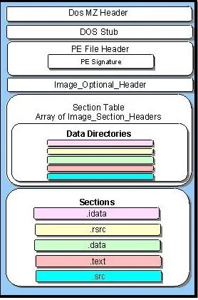
You can see it has lots of headers, which describe different aspects of a program and two major sections - text (containing the code itself) and data (containing all the constant definitions and allocations). Each executable can also contain resources like images, sounds and others - if needed.
We all know how to write a program in, say, C. But how a program in C (or any other language) is “understood”
(and thus, executed) by a processor? One may have heard of Assembly language. This is a low-level programming
language (in opposite to C, which is a high-level programming language). “Low-level” means that a programmer
writes instructions for the processor in the order processor will pick them up and execute, one by one, exactly as
they are set in a program, ommiting syntactic sugar constructions like loops, if-then-else operators and so on.
Usually in such programming languages programmers operate memory addresses and numbers only.
On the other hand, high-level programs, containing all the syntactic sugar features, are first translated
to something processor can “understand” and execute - processors commands (instructions). The program is also being
in terms of removing unused and unreacheable code, replacing expressions which can be pre-calculated into the results
of pre-calculation (like the expression x * 2 * 32 could be simply written as x * 64 or x << 4, which most
of the compilers will do by default because of performance reasons - binary shift operation is way more faster than
multiplication; but for programmer it might be required to stay explicit in order to highlight some calculations or
just to stay clear for other programmers).
Let us have a look at how programs are compiled. Consider this program in C:
int product(int a, int b) {
    return a * b;
}
It will be compiled into this assembly code:
product(int, int): # @product(int, int)
  imul edi, esi
  mov eax, edi
  ret
Looks simple, huh?
In essence, each line of a program in assembly language looks like this:
label: command operand1, operand2 # commentBoth label, operands and comment are optional with the exception that operands requirements depend on command.
Operands could be either numbers, registers (refer to processor registers) or memory addresses.
Registers represent cells in processor memory, those are very limited in number and size, but are directly accessed by processor and thus are very, very fast. There are eight general-purpose registers, common for majority of processors: AX, BX, CX, DX, SP, BP, SI, DI. There are other registers, but we will cover them later. Each command will store its result in one of these registers. These registers have size of one word (2 bytes, 16 bits). Each register has “lower byte” and, correspondingly, “higher byte” - for AX they are AL (low) and AH (high), representing first and last 8 bits of a register. These registers are available for all 16-bit processors. More modern 32-bit processors have extended versions of each register, for AX it is EAX, for CX its ECX and so on. They are twice as big as their non-extended versions (32 bit, 2 words). Nowadays 64-bit systems have extended versions of extended registers, having 4 words and precended with letter R: RAX, RBX and so on. There are also 16 registers worth 128 bit each, XMM0 .. XMM15.
Addressing memory refers to the computer’s RAM; in order to operate with RAM processor first copies the data from RAM to its registers and then performs operation on data in registers. Processor is unable to operate with RAM data directly. You can see clearly such operations require additional actions from processor, namely - copy data from RAM to registers before executing operation and copy the data back to RAM after the operation execution (usually this step is stated separatedly by a programmer). This is time-consuming. And since RAM is not that fast as processor’s registers, it makes operations slow. Memory is addressed using one of these syntaxes:
[address] ; [0x12345]
[register] ; [RAX] - takes address, contained in register RAX
[register + number] ; [RAX + 2]
[register + register * number] ; [RAX + RBX * 3]
[register + register * number + number] ; [RBX + EAX * 4 + 3]
You can also do more tricky thing: define a named constant - give a literal name to a number and then refer to a value by its name. But first you need to reserve a memory for it:
constant_name: db 0x123 ; define one byte value (0x123) and give it a name "constant_name"
constant2: dw 'ab' ; define one word (two bytes) of values 0x61 and 0x62, correspondingly
const3: dd 'abcd' ; define double-word (four bytes)
const4: dq 0x123456789abcdef0 ; 8-byte wide constant
const5: dq 1.234567e20 ; double-precision constant
const6: dt 1.234567e20 ; extended-precision constant
Note I’m constantly mentioning numbers, but never characters or strings. That’s because eventually all this data is just a number (character code or a pointer to a memory - effectively, an address of a memory). And processor can only operate on numbers, nothing else. Compiler will convert all these characters and floating-point values to hexadecimal integer values anyway.
You can also reserve a bunch of memory cells using res command:
const1: resb 2 ; reserve 2 bytes
const2: resw 16 ; reserve 16 words
const3: resq 7 ; reserve seven 8-byte cells
This way each constant will point to the first of the reserved array’ cells in RAM.
Let’s take a look at our example again:
int product(int a, int b) {
    return a * b;
}
Its assembly code is:
product(int, int): # @product(int, int)
  imul edi, esi
  mov eax, edi
  ret
This program has exactly three effective lines:
imul edi, esi ; multiply the data in two registers, EDI and ESI and store the result of multiplication in EAX registermov eax, edi ; copy the data from EAX to EDIret ; restore pointer to the currently running command and the values in registers from stackSee, assembly is still a somewhat high-level language - one command does a little bit of “magic” like
storing the result somewhere, or restoring the processor state (ret) or storing its state and moving to the
different command or sub-routing or function (call). Each processor has its own set of commands, which might
be more optimized for this particular processor. That’s why it is really hard to get each program run best
on all possible computers when distributing it. But the “basic set” of commands is quite common for majority
of processors and you can be quite confident about them.
So after the program is written in Assembly (which is the lowest reasonable language we can more or less easily write code in) it is compiled into… something… Binary code is what you might have been thinking of. And you are totally correct - programs are essentially just a set of ones and zeros. But more interesting question is how a computer executes them?
If we compile our function into binary file - we will get each Assembly command translated into a long hexadecimal (or binary - if you split a long list of ones and zeros into chunks of 16 digits - you will be able to write them down as one character, which is much more compach, right?) value, describing the opcode of a command and its arguments. Each Assembly command has its own code, just like character in a string. And each register has its own code too. Combine them - and you will get a long number. Convert it to binary - and you will get a line of machine codes.
Processor then reads the operation code and acts exactly as it says - if it would be imul RAX, RBX - processor
will do just exactly as it says - multiply the value in register RAX by the value in register RBX and then
save the result in register RAX. To explain how processor actually multiplies values from registers and stores
them - we need to go one level lower - and get familiar with how processor does that on the electonics level.
But we won’t do that. Instead, we will just scratch the surface by describing how fast those operations could be.
You might have heard about processor’s frequency or clock rate. This is a number, showing how frequently an electronic impulse is sent over all the processor’s schematic to enforce its state update. Effectively, what it means is each processor operation like multiplication, addition, subtraction, moving the data around and others, need to change the state of different electronic components, mainly - triggers and transistors. When talking about addition of two registers, for example, processor will need to calculate the sum of each bit pair in registers given, handling overflows, different register lengths and clearing the state of the resutl register beforehand. Some processors are designed to do that in one cycle, but mainly addition will be done in several clocks. Hence a processor with a clock rate of 1 GHz will not make 1 billion additions, subtractions, multiplications or other operations per second. For a reference, here is a diagram, showing how many clocks does each operation takes in average
Remember I have mentioned optimization a while ago? Here’s a sample table of how many clocks do some processor instructions take (in average):
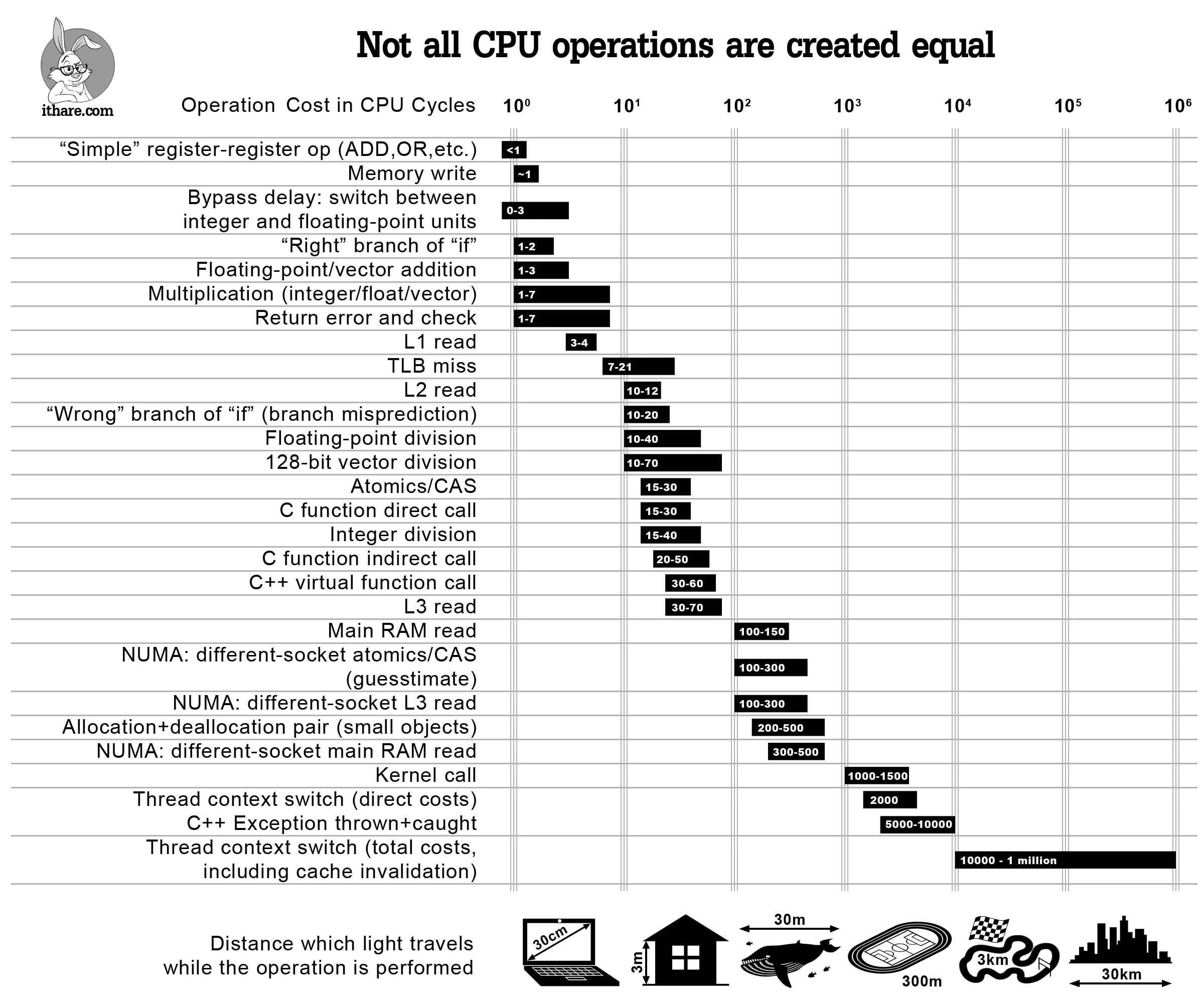
With this knowledge we can easily talk about more high-level things.
Based on How stuff works